


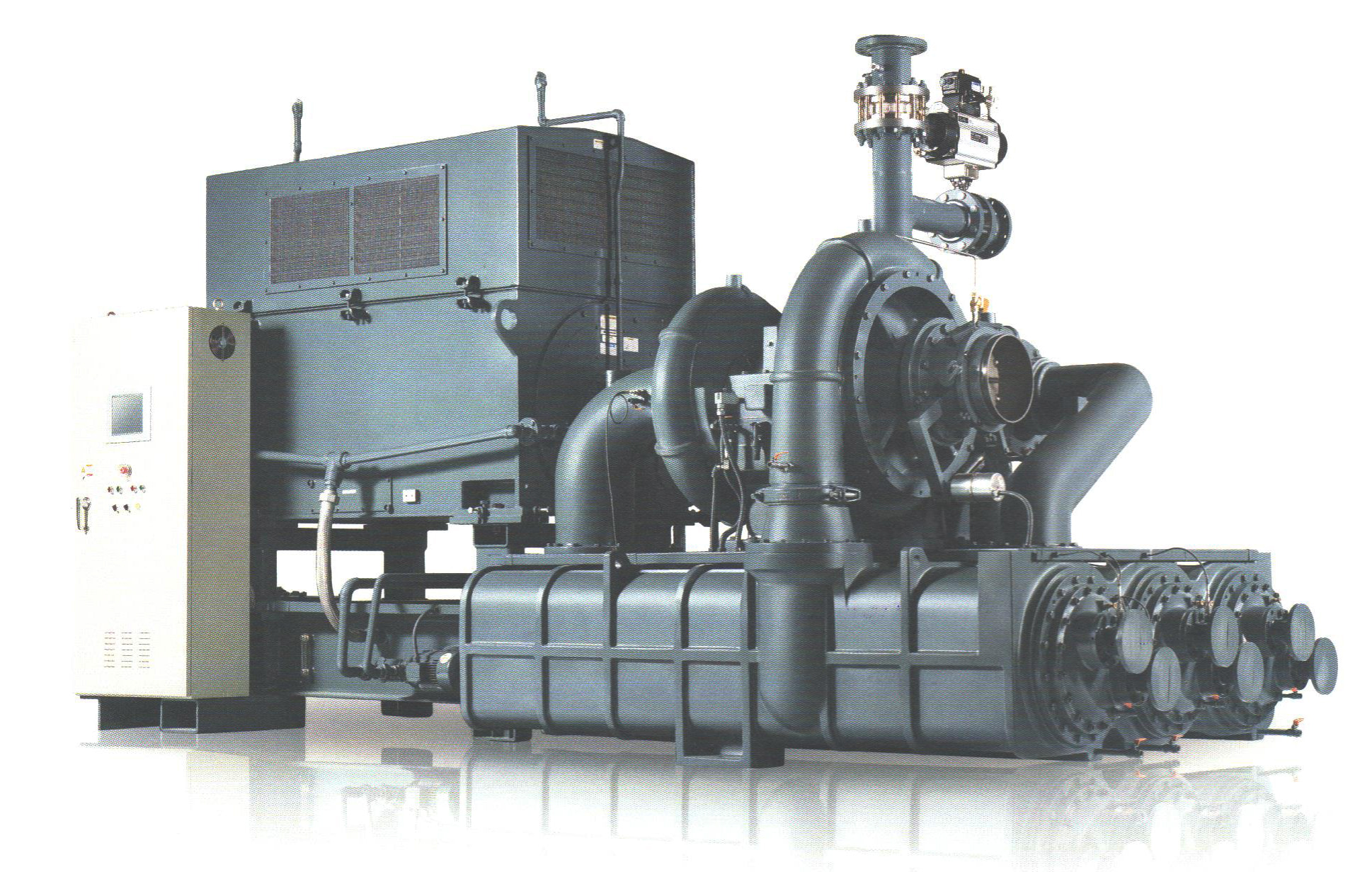
CHORUS Turbo compressor
CHORUS Turbo Compressor
SEAH INDUSRTRY

 Innovative performance & Design
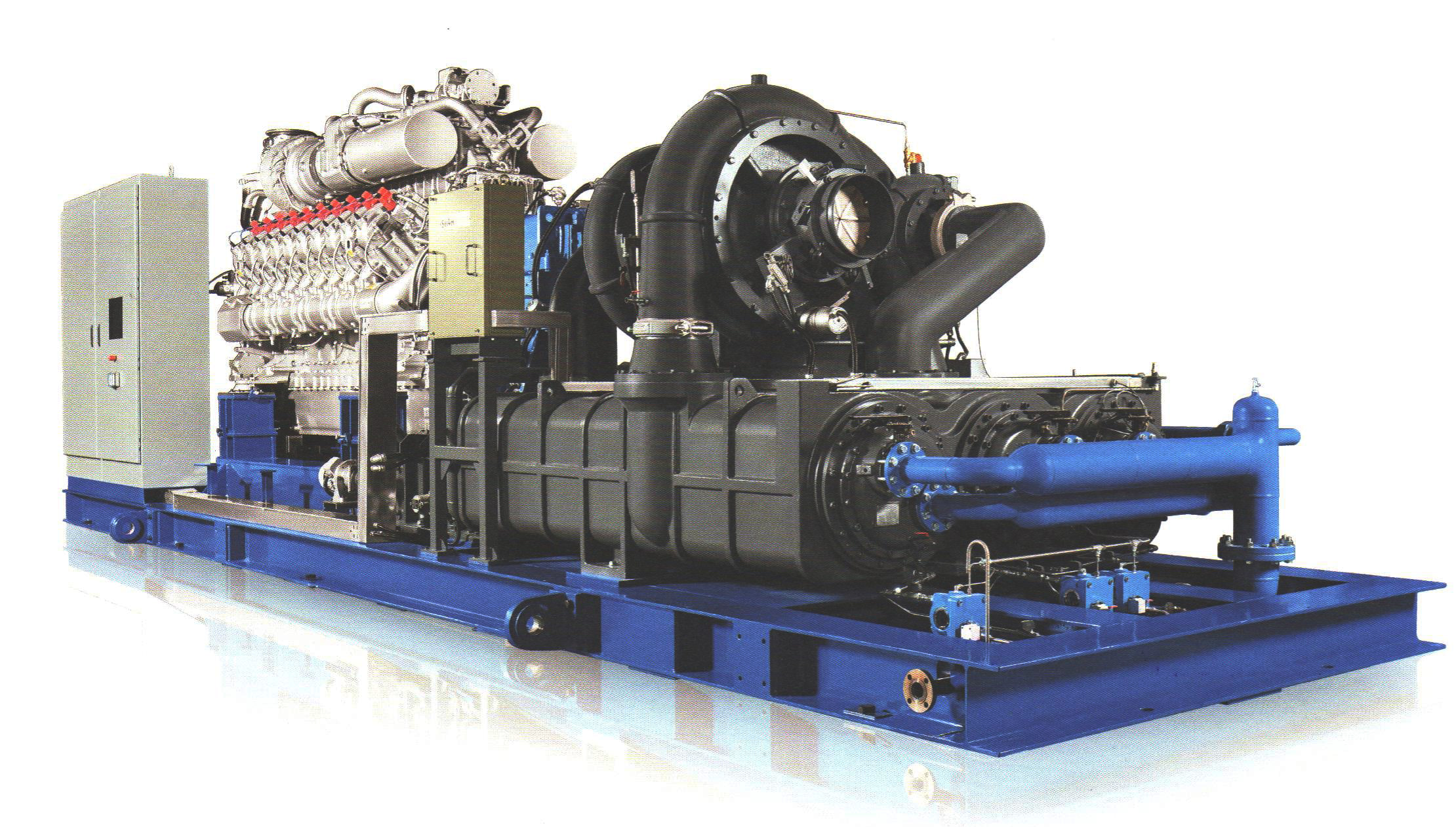
. Featuring inter & after cooler and Lub.oil system structrally separated from
compressor core unit ;
- Simple and compact design and noise minimized operation by adopting sound enclosure(option)
. Featuring 100% oil free and contamination free compressed air, it also provides ;
- Complete structural separation between lubricating and air compressing parts
. Maximum efficiency and quality safety are achieved by ;
- High efficiency design based on state-of-the-art computer simulation methods
- Adoption of the best quality components
- Reliability verification by 115% over speed spin test
. Plug & provides economic and Quick installation
- By immediately available single packaging design integrated after cooler
 Easy Maintenance
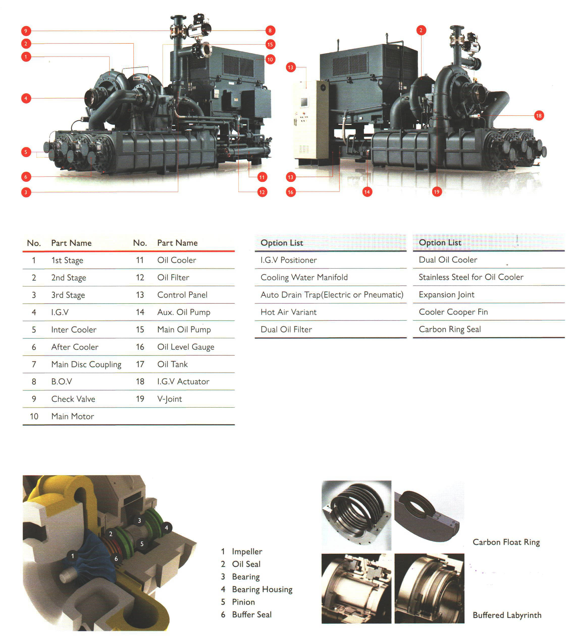
- By adopting horizontal split type gear cases, bearings, and air & oil seals
- Conventenance by adopting straght type water in tube bundles for inter & aftercooler
- Innovatively reduced hours of maintenance by module type design applied for all major components
Indefinite Durability
- By Implementing strict quality control and test for all the main components
- Achieving impeccable durability and stability by established strict quality assurance system
for compression capability essential for stable operation
Optimal components High efficiency impellers Suction control device ( I.G.V ) Vibration monitoring system for each stage Horizontal split type gear case High efficiency main motor Lube system conforming to API 614 Surge control protection Modulating control PLC control panel (9.7" Touch screen) |
|
|
|
Application Process compressor Instrument compressor ASU Booster compressor Vacum compressor One or multi stage compressor |
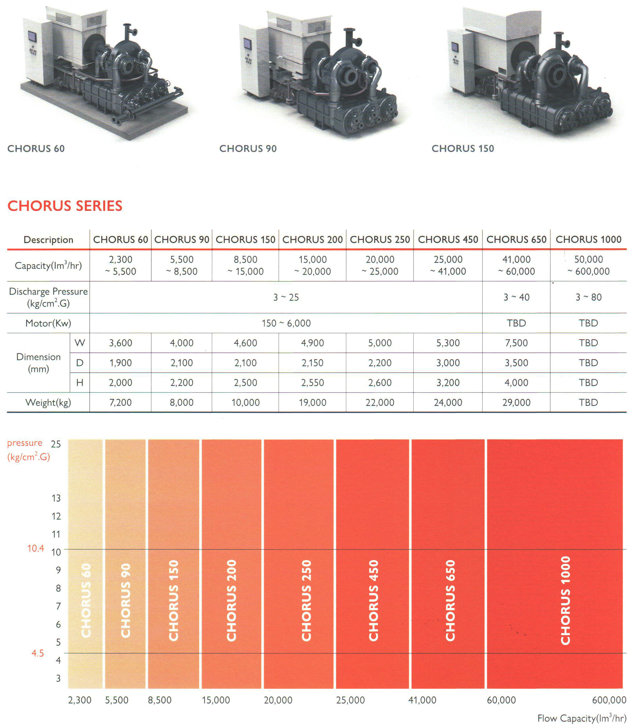
 Model line-up & Specification
※ Be careful that above specification can be changeable at any time without any prior notice
in order to to upgrade the quality and performance of the products.
Description | CHORUS 30 | CHORUS 60 | CHORUS 90 | CHORUS 150 | CHORUS 200 | CHORUS 250 | CHORUS 450 | CHORUS 650 | CHORUS 1000 | |
|---|---|---|---|---|---|---|---|---|---|---|
Capacity(㎡/hr) | 2,100~2,450 | 2,450~5,500 | 5,500~8,500 | 8,500~15,000 | 15,000~20,000 | 20,000~25,000 | 25,000~41,000 | 41,000~60,000 | 50,000~600,000 | |
Discharge Pressure (kgf/㎠G) | 2~8 | 3~25 | 3~40 | 3~80 | ||||||
Motor (Kw) | 140~260 | 150~6,000 | TBD | TBD | ||||||
Dimension (mm) | W | 2,650 | 3,600 | 4,000 | 4,600 | 4,900 | 5,000 | 5,300 | 7,500 | TBD |
D | 1,550 | 1,900 | 2,100 | 2,100 | 2,150 | 2,200 | 3,000 | 3,500 | TBD | |
H | 1,650 | 2,000 | 2,200 | 2,500 | 2,550 | 2,600 | 3,200 | 4,000 | TBD | |
Weight (Kg) | 5,900 | 7,200 | 8,000 | 10,000 | 19,000 | 22,000 | 24,000 | 29,000 | TBD | |

 The principle of compressed air for turbo compressor
During the air compression, inlet air from inlet port is filtered through suction filter, the suction rate of air is
controlled by I.G.V(inlet guide vane) and then, it is supplied into first stage compression part.
The principle of compressed air is that the centrifugal force to rotate impeller at high speed accelerates the air
and then, fixed diffuser is changed to pressure.
The R.P.M(revolutions per minute) of impeller is greatly increased by utilizing the difference of gear ratio between
bull gear and pinion gear of the R.P.M of main motor.
Compressed air to be increased to about 2 bar at 1st stage is cooled through inter cooler at first stage and then,
is supplied into compression part at second stage.
Cooled air is compressed by second impeller, rotating same speed as first impeller and then, is cooled after
supplied into second inter cooler.
Compressed air to be supplied into third stage compression part is compressed again by impeller and is reached
to optimal design condition through after cooler.
Compressed air to be reached to the finally required pressure condition is supplied into each air receiver tank
through D.C.V(discharge check valve) in order to protect the reversal of compressed air in the turbo compressor.